Stereophonic Sound from a Single Loudspeaker
Some methods of using a single loudspeaker to reproduce stereophonic sound in a small room acoustic space.
General Principle
This single loudspeaker consists of one closed box which has speaker elements on three sides.
The stereophonic sound in a small room acoustic space at the listening position is generated by appropriately signaling the three speaker elements, and by employing the benefit of first room wall reflections.
The general speaker element signals are presented below. The variable parameter x can be used to select the operation method. The values of x are between 0 and 1.
The element directed at the listening position gets the signal x L + x R. The element directed at the left side room wall gets the signal L - x R, and the element directed at the right side room wall gets the signal R - x L.
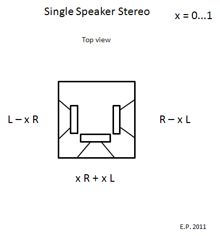
Next is presented some cases depending on the value of x:
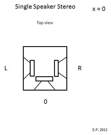
Single Speaker Stereo x = 0
By selecting x = 0 the speaker element signals are as presented below. The element directed at the listener has no signal at all. The side elements get the left and right stereo signals, L and R, directly.
This is the sideways bibolar stereo projection.
Single Speaker Stereo x = 0.5
By selecting x = 0.5 the speaker element signals are as presented below.
This is a vector steered speaker and the signal amplitude and phase for each speaker element depend on the left and right stereo signals L and R .

Single Speaker Stereo x = 1
By selecting x = 1 the speaker element signals are as presented below.
This is the MS stereo. The element directed at the listener gets the mid sum signal, and the side elements get the side difference signal.

Element Connections for Single Speaker Stereo with selectable mode x = 0 and x = 0.5
By using the following simple 'star' element connection circuit it is possible to select the mode between x = 0 and x = 0.5 with the switch.

Single Speaker Stereo with x = 0.5
I believe the optimum value for x is between 0 and 1, and thus x = 0.5 is selected as a starting point for experimenting.
Below is presented a conceptual diagram of the amplitude and phase of the speaker element signals depending on the stereophonic amplitude panning.
Some remarks:
* Mono: L=1, R=1. All three elements get positive signal, and most of the signal is aimed towards the listening position. This produces a real mono source.
* Half left side amplitude panning: L = 1, R = 0.5. The most of the signal is directed at the 45 degree angle at the left hemisphere. The element at the opposite side gets no signal at all.
* Full left side amplitude panning: L = 1, R = 0. The most of the signal is directed at the left hemisphere. The element at the opposite side gets a small negative signal.
* Phase reversal: L = 1, R = -1. No signal is directed at the listening position.

Comparison with a Classical Three Speaker Stereo System
An intuitive comparison is made between the single speaker stereo in a small room acoustic space and a classical three speaker stereo system. Traditionally a three speaker stereo system consists of a linear matrix to generate the signal feeds for the three speakers. A typical value for x could be about 0.5.
Considering the single speaker stereo as a system designed to operate in harmony with the listening room some similarities can be observed between the single speaker stereo and the three speaker stereo systems from the figure below.

Psychoacoustic Filter for the Single Speaker Stereo with x = 0.5
The purpose of the psychoacoustic filter is to steer the high frequency energy from the center element to the side elements.
The passive filter is formed by connecting series RC in parallel to the center element. The values of R and C depend on used elements, the room side wall frequency dependent reflection coefficient and other things so the values must be determined experimentally.

Below is a simulated response (ideal case) of the psychoacoustic filter for center panned stereo signal i.e. L = 0.7 and R = 0.7.
Blue = output of the center element
Red = output of the right element
Green = output of the left element. Note: right and left element signals coincide.
It can be seen that the center element signal is low pass shelved, and side element signals are high pass shelved.

Below is a simulated response (ideal case) of the psychoacoustic filter for hard left panned stereo signal i.e. L = 1 and R = 0.
Green = output of the left element.
Red = output of the right element
Blue = output of the center element. Note: center and right element signals coincide.
It can be seen that the panned side left element signal is high pass shelved, and center and non panned side right element signals are low pass shelved.

Below is a APLAC simulation schematic of generate the above plots.

Recommended Room Placement and Listening Position of the Single Speaker Stereo with x = 0.5
I recommend placing the single speaker stereo along the longitudal center line of the room. This ensures lateral symmetry.
The optimal listening area is not too close to the speaker but there appears to be a minimum distance formed by an approximate circle running through the speaker, the two side walls and the listening position, as scetched below.

Current Prototype of SSSx5
This is a prototype of the Single Speaker Stereo with x = 0.5 (SSSx5)
Speaker elements are Mark Audio Alpair 5. This element has good performance in the most important audio frequencies - midrange and top end.
A separate bass is used with cross over around 200 Hz.
The box dimensions are 40*20*33 cm (height * width * depth). The size of the side panels seems to have some relevance on the directional performance in the midrange as the purpose is to steer the directivity according to the stereo signal and it may be helpful to employ the directional gain from the side panels. There should exist an optimal outside dimensions for the box where directional properties are optimal. This is to be determined...
Below is the SSSx5 prototype placed on top of the bass speaker serving as a base.

Directivity Plots of SSSx5
Measurements is done in a room loudspeaker placed as far as possible from room walls to minimise reflections. Measurement distance is 1 m.
Impulse responses for each angle are analysed with psychoacoustic ERB wavelets (Equivalent Rectangular Bandwidth), and directivity plot is derived from them.
These are raw speaker responses without any equalisation. A 200 Hz high pass is used to protect the elements.
Below is 360 degrees horisontal directivity plot of SSSx5 with monophonic signal conditions L = 0.7 and R = 0.7.
It can be seen that most energy is concentrated in the central angles and are directed forwards.

Below is 360 degrees horisontal directivity plot with stereophonic hard right panned signal conditions i.e. L = 0 and R = 1. Negative angles indicate left and positive angles right hemisphere.
It can be seen that the energy is directed to the right side hemisphere, as it should with right side stereo panning.
Note that the small amount of energy in the left hemisphere should be at negative polarity according to the matrix equation, but the phase of course cannot be seen from this magnitude plot.

Subjective Listening Impressions of this Prototype of SSSx5
Alpair 5 seems to have raising response towards high freqs. This was equalised to have more flat response of the direct sound. Also there might be some issues above 10 kHz with Alpair 5, and a notch filter was placed just above 10 kHz. After these equalisations the performance improved considerably.
The psychoacoustic filter (see the explanations above) helps and I recommend it. With the filter installed the stereophonic imaging performance improves notably.
One very important feature appears to be the fact that the sound arriving via the side wall reflections between left and right side are somehow decorrelated. The decorrelation is achieved by slight asymmetry of the room. In addition of the direct reflection from the side wall, there will be second order reflections from ceiling -> side wall, floor -> side wall and front wall -> side wall. Thus from either side hemisphere there will be arriving a cluster of reflections instead of only one.
This has several important effects:
1) There is no perceivable comb filtering interference field at the listening position like there is with conventional stereo triangle notable especially with pink noise. There is no perceivable tonal balance change with head rotation.
2) The phantom images are extremely stable. One is able to rotate one's head all the way 360 degrees without collapsing the phantom image ! Impossible to achieve the same level of position independency with conventional stereo triangle.
3) The loudspeaker cannot be localised as a sound source with music signal. This is very important feature and is a key to realistic reproduction. The speaker cannot be localised even when moving laterally or with head turning. In this regard I find the performance of SSSx5 much better than with conventional stereo triangle where even slightest lateral movements or head rotations break the phantom imaging illusion and in the worst case the speakers become itself as audible sound sources. With SSSx5 this is not a problem.
4) The ASW (apparent source width) is bigger the loudspeaker itself could output. This is true also for ASH (apparent source height) which is also bigger than conventional stereo triangle could generate.
Thus the phantom images are not miniature pin points like often described with conventional stereo configurations (pin point imaging) but phantom images are having bigger size, not overly big, but matching the size of real sound sources one could image perceiving in a real acoustic event. In this regard of image size I consider SSSx5 more realistic presentation of the original performance than conventional stereo triangle.
5) The sound of the SSSx5 is spacious, more so than with speakers in conventional stereo triangle. Still it is not unnaturally reverberant but just nicely adding sensation of space. This is believed to be due to the increased lateral energy of the stereophonic S (side) signal which is launched sideways from the SSSx5, since it is known that lateral energy mainly contribute to sensation of space. Also in a good recording the 'space' is mainly contained in the stereo S signal.
There is practically no sweet spot. As long as the distance to the speaker is not too short the sound balance and phantom imaging is almost the same overall in the room.
It should be obvious that the side walls in the front part of the room act essentially as sound projection screens and they should not be damped but left reflective. Some slight amount of diffusion might be allowed, but bare walls also seems to do well.
After being listening to the SSSx5 for a couple of months, and occasionally switching conventional stereo triangle speakers on for a comparison, it is really hard to accept the limitations of a stereo triangle. Some essential was missing in the stereo triangle that has now being fullfilled with SSSx5.
SSSx5 is not perfect. But it has opened another dimension that was earlier hidden, and it has clearly shown what else can be achieved with stereophony by doing things differently.
Prototype of a Single Speaker Stereo with x = 0.5 Using CHR-70 Full Range Elements
This loudspeaker is intended to be placed on the wall and is to be used with a TV screen.
Mark Audio CHR-70 is a nice affordable full range element.

The box is constructed of pine wood. It has a volume of about 11.5 l. All the elements share the same internal volume.
Note: In the picture the box is placed bottom up showing the cable connectors and the passive psychoacoustic filter components.
The left view.

The right view.

The speaker is placed on wall for measurement purposes.

The final installation.
Chromed steel fan grills are placed to protect the elements in an 'hazardous environment' :)

The view of the single speaker stereo behind the TV.

Directivity Plot of the Single Speaker Stereo with x = 0.5 Using CHR-70
The directivity plot is measured by placing the speaker and omni microphone in the middle of the room to minimise room influence.
Measurement distance is 1 m.
Impulse responses are analysed with ERB wavelet, and directivity plot is generated from measurements at different angles.
The plots are unnormalised showing frequency response undulation due to some first room reflections, mostly the floor and ceiling reflections.
Directivity plot for a center panned stereo signal i.e. L = 0.7 and R = 0.7.
Interesting to note the psychoacoustic filter action in the treble range attenuating the center sound and emphasising the side sound.

Directivity plot for a hard left panned stereo signal i.e. L = 1 and R = 0.
Over the whole frequency band the signal is steered to the panned left side (negative angles).
Notice the little amount of signal at around 45 degrees at the non panned side, which would be about the angle of the side wall reflections. This is good as very little sound would be reflected from the 'wrong' side.
Remarkable is the ability to steer the signal down to the lowest frequencies, even at 100 Hz signal steering is functioning as intended !

Early Prototype of the Single Speaker Stereo
For fast results as a proof of concept a prototype was build using Visaton FRS8 fullrange elements and a cardboard box.


Some construction photos: Two layers of cardboard is clued together to rigid the structure, and foam is clued at the walls to dampen the vibrations.


Ready ! :)

Preliminary Listening Results from the First Prototype of the Single Speaker Stereo with x = 0.5
Preliminary listening tests with the single speaker stereo have started with selected operation mode of x = 0.5.
The first impressions are positive !
Compared to a conventional two loudspeaker stereo triangle the single speaker stereo has some distinctive qualities:
* The center image is extremely stable and natural sounding. This is believed to be due to center location of the real sound source in center panned image.
* Turning of the head at the listening position has no effect whatsoever on the sound. I can turn my head in any direction 360 degrees and sound image remains constantly in it's original location. Try this with conventional stereo triangle.. hehehe ... ;)
* Walking around the room has negligible effect on the sound. No or almost no sweet spot.
I'm glad to announce that the principle of the single speaker stereo is working !
And this is all from a simple cardboard prototype ! Can you believe !?
Clearly this principle of reproduction of the stereophonic recordings is doing something fundamentally very right in terms of satisfying human psychoacoustics.
more to come ...
Some Remarks on Listening Results from the First Prototype of the Single Speaker Stereo with x = 0
With the selected operation mode of x = 0 (bipolar sideways projection) the sound differs considerably from the vector steered case of x = 0.5.
Operation mode x = 0 produces very spacious sound but in some occasions stereo imaging is also nonexistent. In this regard operation mode of x = 0.5 proves to be much better !
I may even come to conclusion that operation mode x = 0.5 is clearly preferred over the operation mode x = 0 in most, if not all, stereo recordings from natural acoustics classical pieces to studio generated pop songs !
Preliminary Measurements from the First Prototype of the Single Speaker Stereo with x = 0.5
I did some impulse response measurements for the first prototype of the single speaker stereo.
Measurements are done in a 25 m2 room. While measuring impulse responses from different angles, the speaker is rotated in the same location.
Measurement distance is 1 m.
Omni microphone is used for these measurements.
Impulse responses are analysed with Bark psychoacoustic wavelets and the results of the wavelet analysis are shown below.
Single Speaker Stereo with x = 0.5. Panning: Center L = 1 and R = 1
Measurement angle 0 degrees
This is the direct sound for centrally panned sound.

Measurement angle 45 degrees left and 45 degrees right
They are about the same level as 0 degrees sound since this is center panning.


Measurement angle 90 degrees left and 90 degrees right
The level at 90 degrees is lower than the 0 degrees level. In theory it should be lower by 6 dB for center panned sound. A notch appearing at 1.5kHz is propably interference between the drivers, and could be diminished by appropriate cabinet design and element selection.


Single Speaker Stereo with x = 0.5. Panning: Full Left L = 1 and R = 0
Measurement angle 0 degrees
For full left side panned sound the level at 0 degrees is lower than the 0 degrees level for a center panned sound.

Measurement angle 45 degrees left and 45 degrees right
For full left side panned sound a big difference is seen between left and right side angles. Note that the sound radiated to 45 degrees angle is mostly reflected from the room side walls to the listening position.


Measurement angle 90 degrees left and 90 degrees right
For full left side panned sound, the right side level is lower. Also it should be at opposite phase by it cannot be seen from this magnitude plot :)


Conclusions of the Measurements from the First Prototype of the Single Speaker Stereo with x = 0.5
The measurements indicate that the directional pattern predicted from the vector theory can be reproduced by this single speaker stereo.
Some optimisation may be needed to perfect the responses, though.